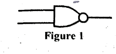
The logic gates represented in Figure 1 is called
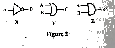
Use the logic gate in Fig 2 to answer question 12.
Which of the logic gates will give an output opposite to the input state?
Use the logic gate in Fig 2 to answer question 13.
Which of the following statements is true about logic gates X and Y?
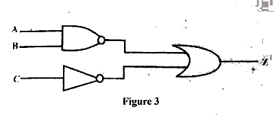
The logical equation for the logic circuit in Figure 3 is
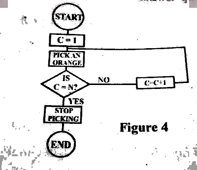
Use figure 4 to answer question 23
The basic problem with the flow chart is that it has
Use Figure 4 to answer question 24
What activity is the flowchart made to represent?
Use Figure 4 to answer question 25
If N in the flowchart is represented by 10, which of the following conditions is not true?
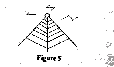
The device is Figure 5 uses a transmission method called
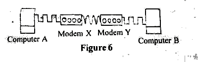
In Figure 6 the signals from modem X to modem Y is
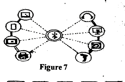
The type of network represented in Figure 7 is called
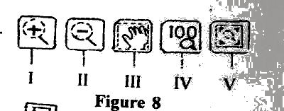
The part of the graphic interface in Figure 8 labelled V is called
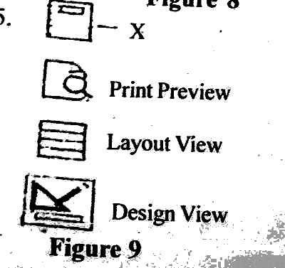
The part of the MS Access interface labelled X in Figure 9 is called
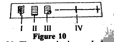
The part of the MS Word interface labelled II in Figure 10 is called
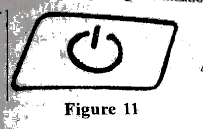
The part of the computer system shown in Figure 11 is used to